Steve Johnson Modelmaker
|
|
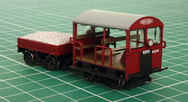
Wickham Type 27 Trolley, with DCC Control Not a locomotive as such, but I thought I would include it as it is a nice little model of these once common and iconic vehicles.
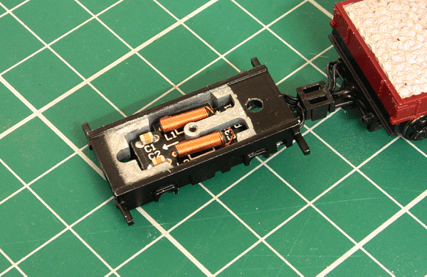
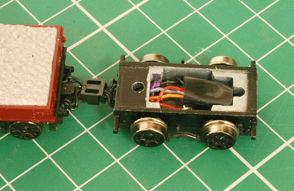
Bachmann have produced the Type 27 Trolley with one of the special wagons with a ballast load. This model is tiny and Bachmann have done a good job in reproducing it in a motorised form. In order to retain the open nature of the Trolley, a permanently coupled wagon is included containing the motor (presumably coreless) and drive hidden under a plastic ballast load. Drive is to the front set of wagon wheels which have traction tyres. I have the earlier maroon liveried version, numbered B 30 W, although the later later yellow is also available. As supplied, Bachmann have stated that it is not DCC compatible. This is not because of the motor or drive mechanism, but more I think, that they do not market a suitable decoder! In fact, when I took the Trolley apart, there was ample room for a mini or micro sized decoder with pins if the design had been thought out a little better. I can only guess that Bachmann do not like to recommend Third Party decoders! Just makes it a little more difficult for us, but not insurmountable. In fact, a number of retailers have already offered a DCC Fitted option, such as Hattons, TMC and Olivia's. Some of these options include fixing the chip to the underside of the trolley's roof (not to keen on that option). Other options include using a a very small decoder concealed in the modified wagon or Trolley. Olivia's even offer a sound option (at £230.00), but the sugar cube speaker sits on the rear seat and is hidden by black sheeting, which to my mind, destroys the 'open' feel to the model. I decided to have a go at fitting a decoder and see how far I would get. I figured there would be little room in the wagon, as it has the motor, so looked at the Trolley itself first. The Trolley and wagon are permanently coupled, more so by the four wires than the push fit plastic coupling. The underside of the Trolley has two very small black screws that hold the body to the chassis. These were unscrewed and the body removed, it just pulls off. What is left is a cast chassis block and a small circuit board.
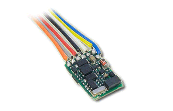
Looking carefully at the space inside the chassis block, I felt it might be possible to place decoder here if the circuit board was removed. Measuring the space revealed that I had at least three options, a Zimo MX621, a CT Electronik DCX75 or a Lenz Mini. I've not tried any Zimo decoders, but understand they are very good, especially with small coreless motors. I have tried CT Electronik decoders a few times, two 'Dead on Arrival', the other three ended up in smoke! They are also tricky to set up and the instructions leave a lot to be desired. So personally, I have not had good experiences with them. This left the Lenz from which I have always had good results. As such, I ordered a wired Lenz Silver Mini+, simply as that what was in stock!
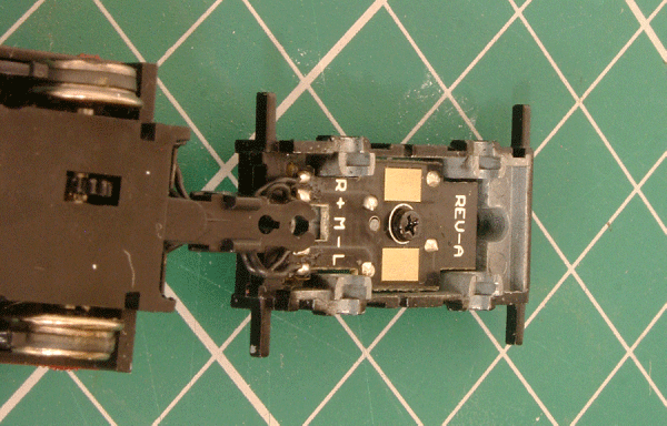
Now to take the chassis apart to work on. The plastic keeper plate needs to be removed. This is held by two plastic clips in opposite corners. Care is needed as the pick ups to the Trolley's wheels are attached to this and are very delicate. The wheels are carried in square brass bearings that locate into the chassis and just lift out. The chassis circuit board is secured by a screw into a arm that forms part of the chassis casting. This has to be removed and the stub filed flush in order for the decoder to fit and besides, with a decoder you won't need the circuit board. The pick and motor wires are soldered to this board and need to be carefully unsoldered with a very fine tip iron. Make a note of which wire is which, but basically the outer pair are track power whilst the inner pair are the motor feed. I felt the easiest way to connect the four leads to the decoder would be by using a small piece of PCB strip board carefully cut to shape to fit around the protrusions in the chassis block. The reason for this is that you have to get the wires underneath a metal axle. The wires from the wagon are quite short and simply soldering the decoder wires to the wagon wires leaves the danger of shorting out on the axle. I found that with the PCB I used, I could get four copper tracks from front to rear. The PCB does not want to be too long, just to clear the axle and some room to solder. Having fashioned this, I glued it to the chassis block and allowed it to set.
Next was to reconnect the wires from the wagon to the PCB in the Trolley. Again, care is needed here in the confined space as well as not shorting out the tracks. When done, a quick check with a continuity meter will show if any inadvertent shorts between tracks has been made. Next is to solder the decoder to the other end of the PCB. As I am using the decoder for motor functions only, I decoded to remove the yellow and white lighting wires in addition to the blue common wire. These were carefully unsoldered from the board. This left the red, black, orange and grey wires which have to be shortened to about 1/2 to 3/4 inch. Although not recommended by Lenz, I decided to wrap the decoder in some insulation tape to prevent static discharges from myself whilst handling and shorting on the chassis when completed. The wires are then soldered to their relative positions on the PCB. Finally, the pick up contacts from the Trolley chassis have to made to the PCB. In Bachmann's design, the small springs touch the original circuit board. Here however, I had to make up some very short wires and solder them from the springs to the PCB. A test with some flying leads can be made now to see if the the unit works. Mine did, so it was a case of refitting the wheelsets. This is quite tricky and patience is needed. Make sure there are no shorts between the axle and PCB. Next is to refit the keeper plate. Careful repositioning will be needed here in order not to deform or bend the fine pick up springs. Make sure the wheels rotate freely and the pick up contacts are touching the wheel backs.
When re-assembled, the unit can be tested. I tested mine first on dc and it moved as it should. Switching to DCC control also controlled the Trolley. Satisfied with this, I re-attached the body having carefully positioned the decoder in the space in the chassis block. Be careful not to short anything out here. I usually like to use a decoder address that relates to the vehicles number, it is easier for me to remember this, as such, I used 30 as the address. Further testing showed that some tweaks to the decoders settings will be needed to optimise performance. For now however, I have a DCC controlled Wickham Trolley with an invisible decoder.
|
